Call 01590 671997

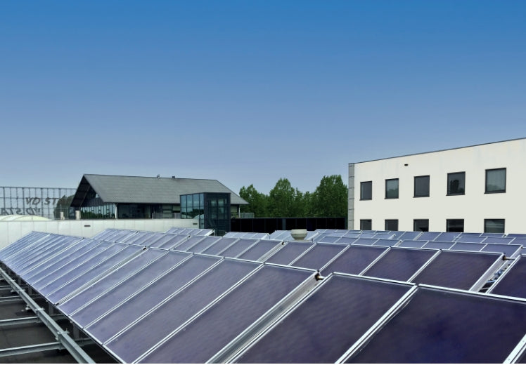
With 20 years’ experience in the design and supply of solar thermal heating systems we are adept at finding the right solution for any given application.
We supply the most efficient, reliable and cost-effective kit so ensure the maximum available lifespan and return on investment for our customers and the end user.
Having stocked evacuated tubes for many years we are currently stocking solely flat plate collectors which, when compared to tubes, now give more output per m2 of aperture area whilst also providing greater reliability and system longevity.


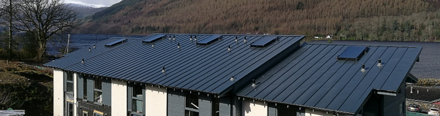
As living costs continue to rise many homeowners are turning to renewables to help reduce energy bills and future proof their properties. We supply domestic solar thermal kits for new builds, retro fit and local authority upgrades (i.e. pre heat systems for existing gas combi boilers). These systems can typically reduce a domestic hot water bill by 60%.
We also supply systems for domestic swimming pools, find out more here.
Need a quote?
Our dedicated technical team will be happy to provide a tailored quote with estimated output calculations and detailed schematics.
Call us on 01590 671997

Find products & kits
Register or log in to browse domestic solar thermal products & kits and get an instant online quote.
Browse products & kits